Weld Symbols Guide 2026 – Types, Standards & Reading Basics
What Are Weld Symbols – Main Concept
The weld symbols are the symbols which you use to decode the welding needs through technical drawings. In fabrications sectors around the globe they refer to as a source of communication for welding technicalities. Symbols identify the size, type, location, and finishing requirements of welds, which are to be correctly done. They enhance clarity, minimize errors, and guarantee uniform interpretation of projects.
Why Welding Symbols Are Important
- Ensure Consistency
All engineering drawings have consistent interpretation of symbols of welding. They are used to standardize communication between designers and fabricators working over worldwide teams. They contribute to less variation and uniform weld quality.
- Reduce Communication Gaps
Symbols of welding minimize misunderstandings between engineering and shop floors teams. They also have good visual guidelines on fabrication procedures. You can witness reduction of mistakes in production and assembly processes.
- Improve Weld Quality
Correct symbols of weld provide clear and precise welding requirements. They help control the weld size, type and location and help in making stronger and defect free joints.
- Increase Safety and Structural Integrity.
Proper symbols for welding eliminate structural failure in critical areas of projects. They also make sure that there is proper distribution of loads along the welded joints. eliminating the chances of accidents and collapses.
- Speed Up Fabrication Processes
Common weld symbols make fabrication and shop work operations much more expeditious. Drawing is understood by workers faster without having to be explained again and again. It saves time and enhances speed of project delivery.
Standards Governing Symbols Used in Welding (AWS, ISO, EN, BS)
The current standards of welding symbols have established a unified system of communication among AWS, ISO and EN systems. AWS A2.4 regulates in the USA, ISO 2553 in other parts of the world, and BS EN 22553 in Europe. Standards have the same symbol logic but vary in the rules of placement and style of reference lines. Proper standard choice leads to engineering clarity, safety compliance and prevents fabrication errors in all parts of the world. The practice in the industry combines old drawings with the new standards that need to be converted with care in the execution of the project.
Standard | Region | Reference Line Style | Key Feature | Usage |
AWS A2.4 | USA | Solid line | Clear arrow-side rules | North America |
ISO 2553 | Global | Solid or broken line | Broken line indicates other side weld | International projects |
BS EN 22553 | Europe | Similar to ISO | Metric-based interpretation | EU fabrication |
BS 499 (older) | UK (legacy) | Solid line | Replaced by EN ISO system | Old drawings only |
Basic Structure of Welding Symbol – Three Main Components
Arrow
The arrow indicates the exact point of the joint where welding should be done. It shows physical location and side of workpiece which needs welding work. Depending on the variation in drawing layout needs, it can be drawn at various angles. It is clearly and efficiently efficient to help welders to know precise joint positioning prior to actual fabrication.
Reference Line
All the information presented in this form of welding symbols is based on reference line. It contains weld type size spacing and configuration information on fabrication work. When complex welding processes are to be done in drawings multiple reference lines can be present. It facilitates effective communication of the requirements of weld to fabricators and engineers.
Tail
Tail This is an optional element of welding symbol that is not always depicted in drawings. It gives additional instructions which do not fit main structure clearly given. When specified, normally includes standards of the type of electrode used in a welding process or special notes. It assists in maintaining the adherence to project requirements and industry requirements that are uniformly implemented.
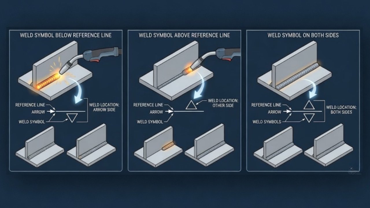
Understanding Welding Orientation
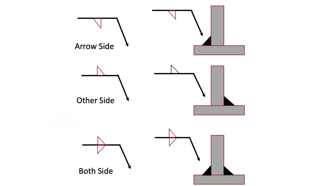
Other Side vs Arrow Side
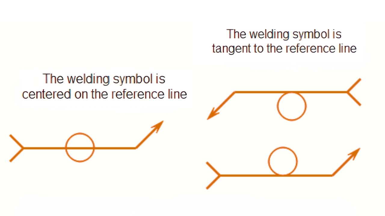
Weld orientation describes the use of symbols in technical drawings to clearly indicate joint position in engineering. Surface pointed by arrow, other side opposite face. Both sides of the weld need to be welded to ensure a better joint.
![]()
Weld Placement Rules
The rules of the placement of the welds are used to interpret the reference lines in drawings of welding. Below reference line shows arrow side where weld has to be put. Above reference line represents other side weld location in drawings. Weld on both sides is represented on both sides of the symbol.
Numbers in Welding Symbols
Welding symbols have numbers that provide the necessary fabrication information in order to prepare joints properly. They are weld size, length, pitch, root opening, angle, and penetration depth specifications. Numbers on the left of symbol usually denote weld size and dimensions associated with the same. Numbers on the right specify length and pitch to separate the welds. Above symbol values indicate the requirements of root opening or groove angle clearly. Numbers below symbols show penetration depth that assures structural integrity and quality of weld. Proper interpretation guarantees safe and reliable outcomes of welding.
Welding Symbol Numbers and Their Meaning
Symbol Position | Meaning | Example |
Left of symbol | Weld size | 6 mm fillet weld |
Right of symbol | Weld length | 50 mm weld |
Right (dash separated) | Length & pitch | 50–100 |
Above symbol | Other side weld | Opposite joint |
Below symbol | Arrow side weld | Same side as arrow |
Inside symbol | Angle / root opening | 45° groove |
Parentheses | Effective throat | (8mm) |
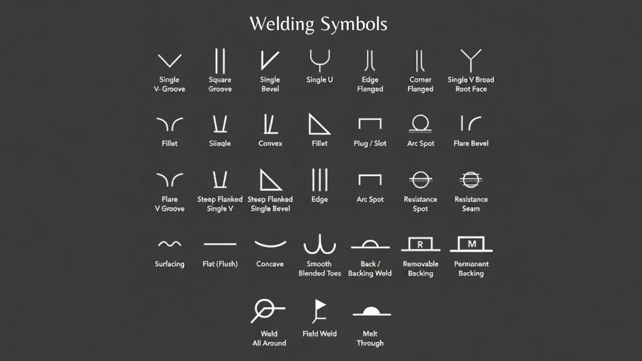
Types of Welding Symbols
- Basic welding symbols
- Supplementary welding symbols
Basic Weld Symbol (Main Types)
Fillet Weld Symbols
The most used type of weld in engineering drawings is a fillet weld symbol. It displays a triangular icon indicating the size and location of weld. Applied to T joints, lap joints and corner joints. Equal and unequal leg welds are used to control the distribution of strength, whereas intermittent welds conserve materials. They enhance structural efficiency.
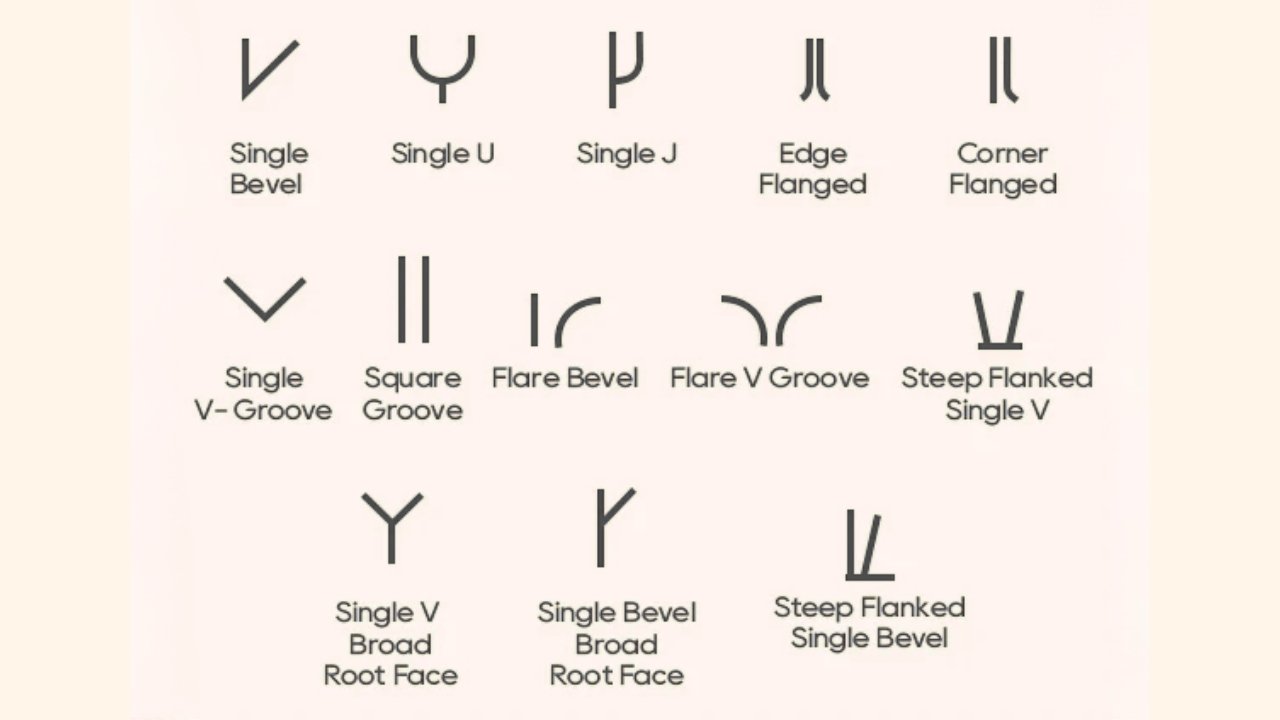
Groove Weld Symbol
Groove welding symbols are used to depict the preparation of joints and aid in specifying the geometry of welds in fabrication drawings. They are square, V, bevel, U, J, flare V and flare bevel groove joints. Groove weld details give details of groove angle, root opening, depth of preparation, and effective throat. These parameters guarantee strength, alignment and weld quality.
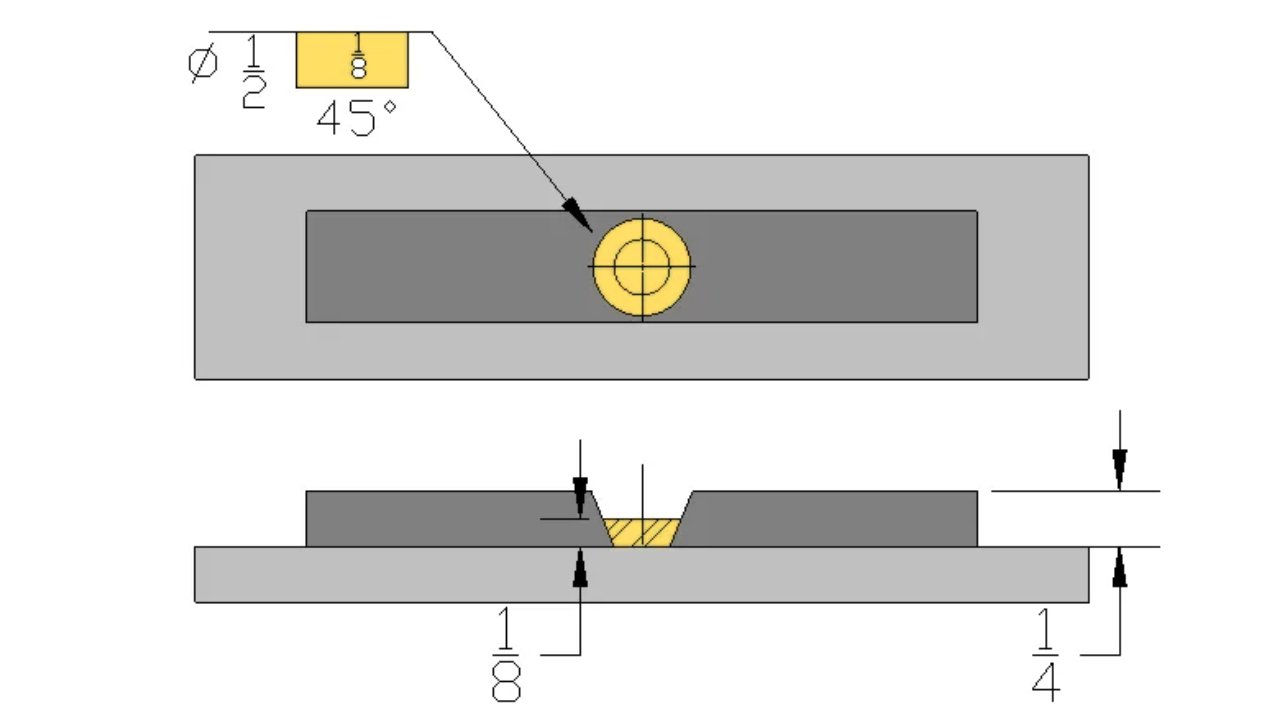
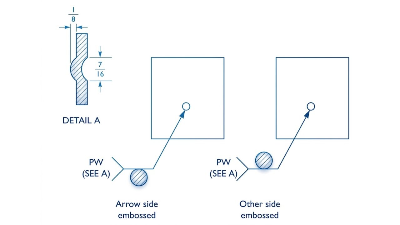
Plug Weld Symbol
Plug weld symbol is the symbol of welds that are made using round holes in plates. It is applied in convergent plates to form strong joints. Penetration of strength and structural integrity in general is determined by size and spacing. You use it by filling holes with weld metal.
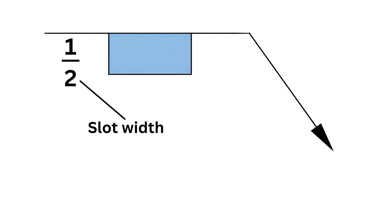
Slot Weld Symbol
Slot weld symbol is used to signify long holes in plates. It resembles plug weld except that it employs slots. It provides good structural ties in fabrication work. You apply it in overlapping joints that demand heavy load transfer and long-lasting weld filling performance.
Spot Weld Symbol
The welding drawings represent the spot weld with a circular symbol. It is applied in sheet metal resistance welding. It is a process that fuses thin materials under localized heat and pressure. You use it in quick strong joints in the assembly line of manufacturing processes.
Projection Welding Symbol
In resistance welding, projection weld symbol is similar to spot weld. It welds with raised projections on metal surfaces. It is typical in mass production of components. You apply it to make various points of welds in one process of operation cycle.
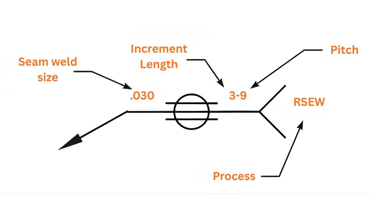
Seam Weld Symbol
In drawings, continuous weld line is represented by seam weld symbols. It is employed in the resistance seam welding processes. It offers metal sheet leak proof joints. You use it in the continuous joining of overlapping sheets in the work system application in industrial fabrication.
Surface Weld Symbol
Surfacing weld symbol refers to accumulation on metal surfaces layers. It is applied in surface restoration and repair. It enhances wear resistance and durability of overall components in a significant way. You use it to regenerate worn surfaces to extend service life and performance on protection.
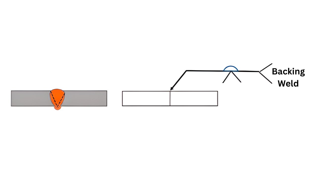
Backing Weld Symbol
Backing weld symbol indicates backing material at the back of weld joints. It helps in molten weld metal in the welding process. It enhances both penetration and weld quality in general. You use it to stabilize welds in thick joint fabrication and assembly work process control.
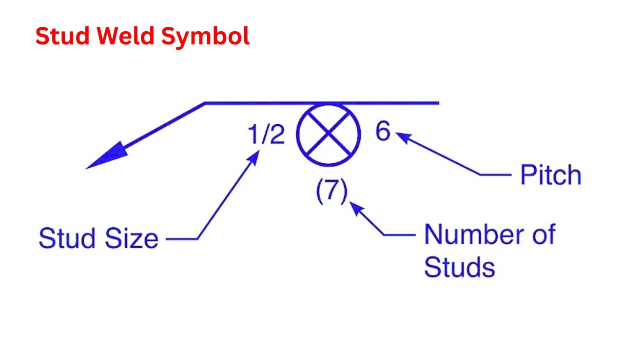
Stud Weld Symbol
Stud weld symbol denotes the attaching threaded or non-threaded studs. It is typical in building and steel-making. It offers good anchoring of structural components. You use it to secure studs on metal surfaces for firm installation process control.
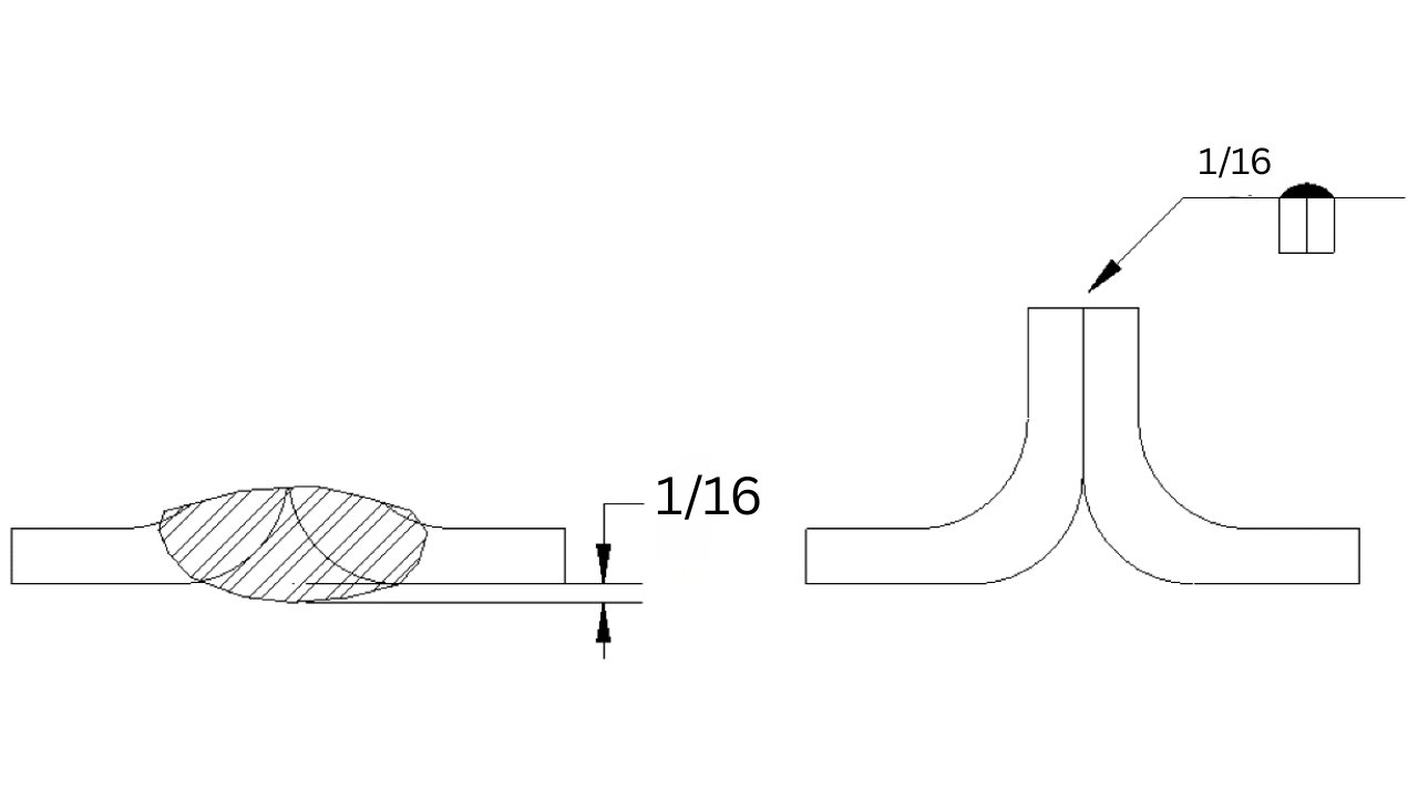
Edge Weld Symbol
Edge weld symbol is used to denote welding on edges of sheet metal. It is mainly used for thin material joining applications. It guarantees clean joints in lightweight structures. Edge weld is widely applied in sheet metal fabrication to strengthen seams applications industry.
Symbol Type | Shape | Application | Common Use |
Fillet | Triangle | Corner joints | Structural frames |
Groove | Various | Butt joints | Pipe welding |
Plug | Rectangle | Overlapping plates | Structural steel |
Spot | Circle | Sheet metal | Automotive |
Seam | Circle with lines | Continuous weld | Tanks |
Surfacing | Half circles | Repair | Hardfacing |
Stud | Cross circle | Stud welding | Construction |
Edge | Rectangles | Sheet metal | Enclosures |
Supplementary Weld Symbols
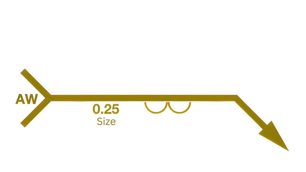
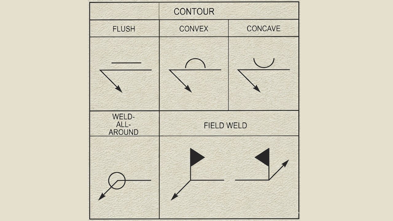
Weld All-Around Symbol
The symbol of weld all-around refers to continuous weld surrounding entire joint on engineering drawings. It uses a circle at arrow intersection ensuring full joint fusion and strong uniform structural integrity reliability performance.
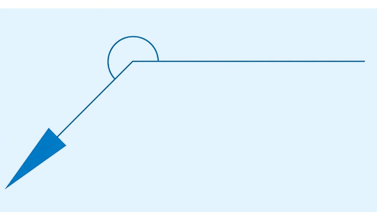
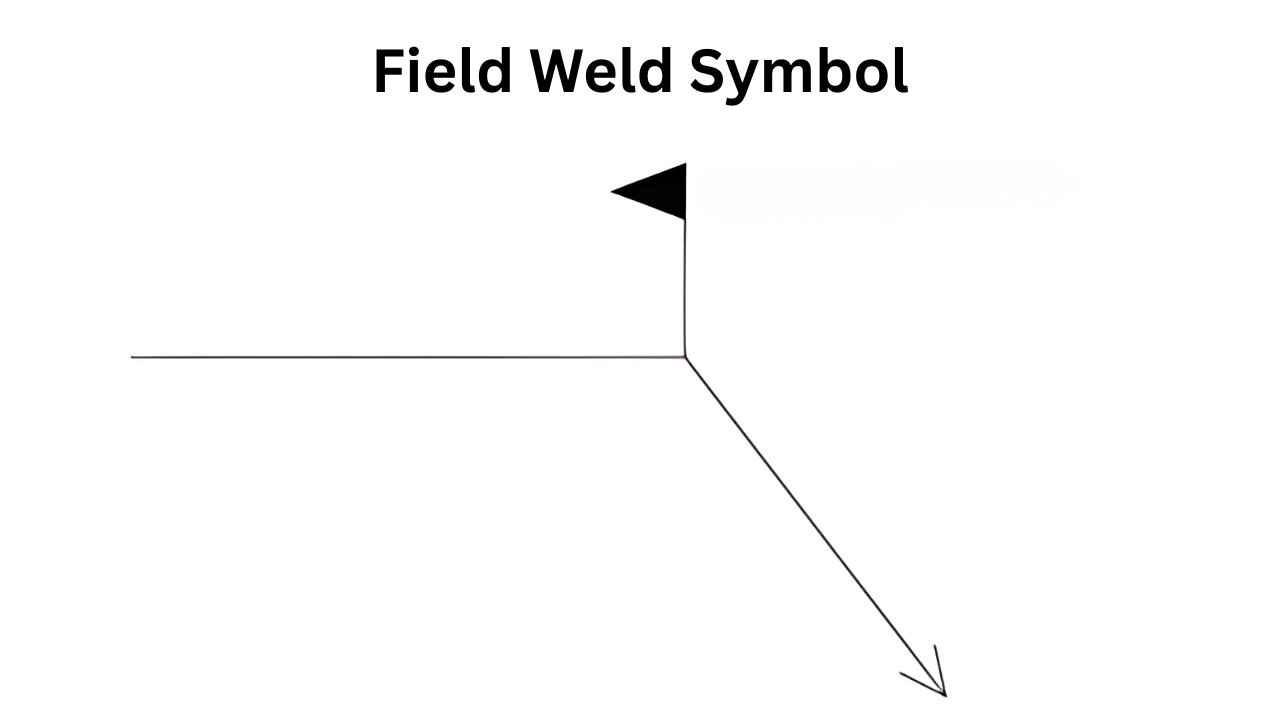
Field Weld Symbol
Field weld symbol is a type of welding that is done outside of a workshop on a construction site. It employs flag symbol at reference line indicating site assembly conditions and practical execution requirements on-site welding requirements.
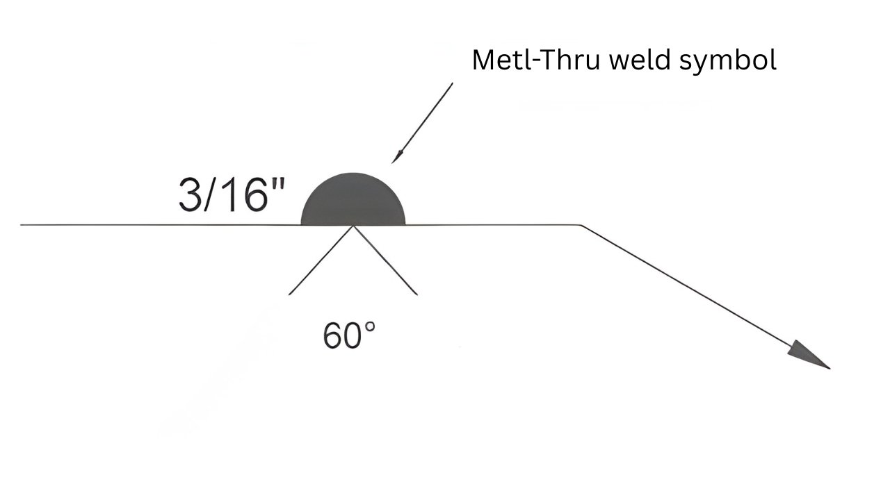
Melting Symbol
The melt-through symbol is used to indicate visible root reinforcement which is full penetration in welded joints. It is placed beneath weld symbol and guarantees backside fusion particularly in quality control assurance in pipe welding.
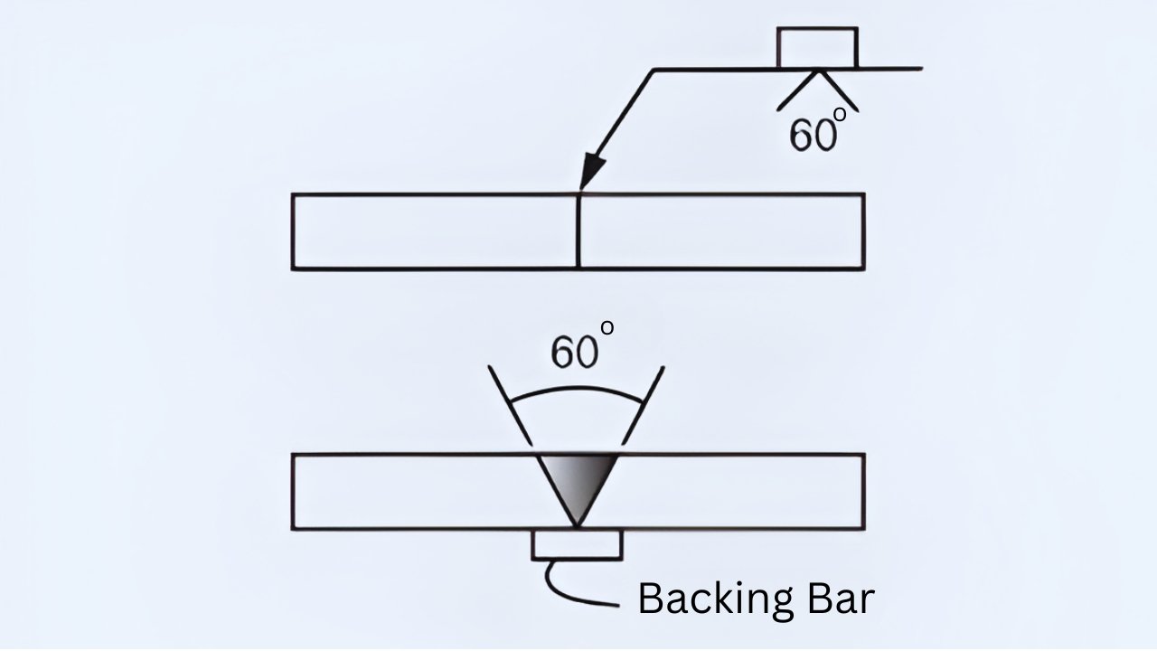
Backing Bar weld Symbol
Bar symbol Backing: Material put behind the weld root to hold molten metal as it melts. It enhances quality of the weld eliminates burn-through and stabilizes root pass in the reliability of the fabrication work process.
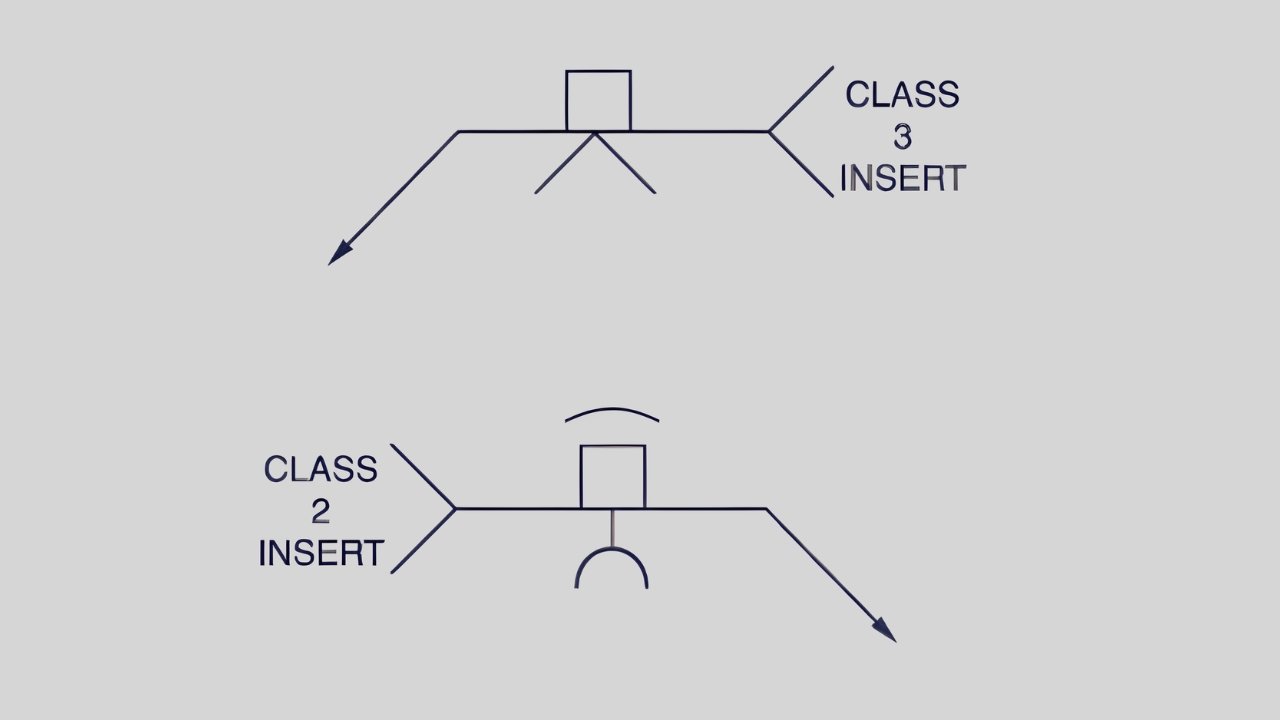
Consumable Insert weld Symbol
Consumable insert weld symbols indicate filler material in the joint root to enhance the quality of welding. Its melting during welding increases penetration and guarantees good root pass in pipes applications performance.
Welding Contour Symbols
Contour symbols refer to the geometry of surfaces including flush, convex, and concave surfaces. Flush surfaces are even in shape whereas convex curves away and inward curves. These shapes affect the structural integrity, the aesthetics and the stress distribution among elements.
Welding Finishing Symbols – Finishing Methods
The finishing symbols are used to show what kind of finishing is to be used to give the desired and specified look or contour of the weld. The specific finishing technique is indicated by a letter that is put above the contour symbol and above the reference line. The letters represent the initial letter of the method of finishing, and these are:
- Grinding (G)
- Machining (M)
- Chipping (C)
- Hammering (H)
- Rolling (R)
- Planishing (P)
- Unspecified (U)
Additional Tail Information – What Goes in Tail
Other tail data specify the welding process characteristics and provide the accuracy of control over the correct identification of joints. Reference standards direct the quality compliance of welds and uniform documentation of projects worldwide. Inspection conditions check the integrity of the welds using visual testing and nondestructive testing. The type of electrode used determines the consistency of arc stability and quality weld penetration.
Common Welding Process Abbreviations
- SMAW: SMAW is Shielded Metal Arc Welding process consumable electrode coated flux. It is appropriate when doing repairs on outside construction sites. Manual operation technique is known.
- GMAW: GMAW is Gas Metal Arc Welding otherwise known as MIG MAG process uses. Welds continuously using wire. Usually in the automotive and fabrication sectors.
- GTAW: GTAW is Gas Tungsten Arc Welding that is used to make clean welds of high quality. Shields with non consumable tungsten electrode. Perfect in thin accurate metal work.
- FCAW: FCAW is Flux Cored Arc Welding process, which utilizes tubular wire electrode system. Appropriate to outdoor windy weather welding work. The rate of deposition is high and this makes productivity high.
- SAW: SAW is Submerged Arc Welding process in which arc is submerged flux layer. Applied in heavy fabrication work of plates. Offers excellent penetration and welds.
Compound Weld Symbols
Compound welding symbols represent various welds on a single joint in engineering drawings that are well defined. They are combination welds, which combine various types of welds to make them strong and durable. Multi-pass welding is used to lay down more than one layer to meet the required thickness and quality control requirements.
Broken Reference Line (ISO Standard)
Broken reference line in the ISO standards of welding means welds on the other-side of joints. The difference between ISO and AWS lies in the conventions of placing symbols, interpreting them and the reference line. It is necessary when specifying alternate side welds to make them clear in fabrication drawing standards.
How to Read Weld Symbols Step-by-Step
Step 1: Find Arrow
Start by locating the arrow on the welding drawing symbol sheet so as to interpret correctly. It identifies the place and direction of joints where weld is required to be applied in the fabrication process accurately.
Step 2: Find Reference Line
Identify the reference line where all the information about the welding symbols needs to be placed or interpreted. The entire information on the type and size of the weld is always with reference to this line.
Step 3: Check Weld Symbol
To decide the kind of weld required such as fillet or groove, identify the weld symbol. It gives the necessary guidelines to the strength of the weld shapes and the preparation of the joints as always required.
Step 4: See Numbers
Compare figures with symbol to find accurate measurement information of weld size and length. They can also exhibit spacing pitch or depth based on design requirements well defined specifications.
Step 5: Examine More Symbols.
Symbols of check supplementary conditions of welding or surface finish conditions were clearly indicated by notes. These symbols assist you in knowing the special instructions such as backing contour or weld all around instructions.
Step 6: Read Tail Information
Read tail information to find the specifications of the welding process or special instructions with clearly stated information. It typically includes statements that clarify procedures materials or codes that are required to be in compliance with the requirements of compliance standards.
Common Beginner Mistakes When Reading Weld Symbols
- Misinterpret Arrow Side: Novices tend to read arrow side of symbols used in welding It causes weld to be improperly placed and misinterpreted. Always ensure reference line and arrow direction are checked.
- Ignoring Numbers: Ignoring Numbers on symbols of welding leads to big fabrication errors. They determine size, length and weld spacing. Always ensure that the numerical values are checked before starting any kind of welding.
- Confusing Weld Types: Confusing weld types is a common beginner mistake often. Different interpretations are needed in fillet, groove and spot welds. Structural weakness and failure can be caused by misidentification.
- Overlooking Finishing Requirements: Finishing requirements are extremely important in relation to weld quality and durability. Surface treatments are usually denoted by use of symbols. By not taking them into account, it is possible to greatly lower the overall weld lifespan.
- Wrong Standard: When the wrong welding standard is used, it can cause a lot of confusion. AWS, ISO and BS systems have different standards. To ensure adequate standards of interpretation, always check documentation.
Real-World Applications of Welding Symbols
Structural Steel Fabrication
The welds symbols are used to make fabricators interpret structural steel drawings properly. These standards make sure you attain safe joints and uniformity of quality in the construction of beams and columns.
Automotive Manufacturing
Automotive symbols of welding are used to standardize the assembly procedures in complex structures of the vehicle body. They are used by engineers to make it durable, precise and maintain the same quality of production as a safety measure.
Shipbuilding
In hull structures that are subject to extreme marine conditions, shipbuilding weld symbols mark important joints. Right interpretation will assist you not to experience structural failure in long voyages operations.
Aerospace
The welding in aerospace should employ precise symbols of lightweight aircraft and high strength. Drawing is to be interpreted carefully so that the safety and regulatory compliance standards are high.
Pipelines of oil and gas.
Pipeline welding symbols report types of joints and inspection necessities of long distance transport systems. Accuracy of reading ensures the prevention of leaks and safety of the operation in harsh environments.
Construction
The symbols of construction weld simplify the communication between the engineers, contractors and site supervisors. Sufficient knowledge reduces errors, improves quality and quality assurance of the project specifications is always achieved.
Tools for Learning Welding Symbols
Welding Charts
Welding charts make sure that you are aware of typical symbols in fabrication drawings. They simplify the interpretation process, make it more precise and guide the appropriate decision of the weld in different joints and materials in the workshops on a daily basis.
Online Simulators
Simulators On simulators, you are able to practice welding symbols with interactive tools on-line. They enhance knowledge, minimize mistakes and assist you to build confidence to work on actual fabrication projects safely at all times online.
Training Programs
Structured welding symbol interpretation is taught by training programs and is taught through guided instruction. You are taught practical applications, industry standards, and practical exercises that reinforce your technical skills at professional welding work continually enhanced.
Blueprint Reading Courses
The blueprint reading courses help you to decode the symbols of welding on technical drawings. The layouts, dimensions and joint specifications are known to you, which makes it more precise and effective in actual-life engineering and fabrication work in a work with a professional application.
Conclusion
Learning weld symbols is vital in proper fabrication, safe structures and uniform communication of engineering drawings and industrial welding projects globally. Novices are encouraged to practice standards of learning, practice charts, and blueprint reading often to attain good interpretative skills and reduce costly errors. With practice and experience, you can learn to master basic symbols of welding and enhance quality and safety of welding in professional practice in the long run. Learning the symbols used in welding guarantees improved careers, increased output, and dependable results of fabrication in the engineering industries in general.