Understanding Sheet Metal Design: Rules & Guidelines (2024)
In recent years, industrial machines have looked like designer home appliances, and their sheet metal covers are often rounded. A sheet metal design that relies on the brute force of welding can result in an expensive structure. Also, we often hear that when looking at the design drawings provided by designers, they are confused about how to design, such as the structure, component composition, and how to cut the product.
Industrial machinery is often manufactured to order, and lead times are becoming shorter each year. Designers at machine manufacturers are extremely busy designing the main body of the machine, and it is said that in most cases the design of the cover is put on the back burner.
So, therefore, once we design a product which is going to be made using a metallic sheet, what are the guidelines that we must keep in mind?
What is sheet metal?
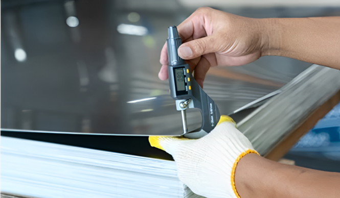
Sheet metal is one of the basic forms of metal commonly used in mechanical processing. They are thin, flat metal plates that are rectangular or square in shape.
It is used to make raw materials for manufacturing parts and components of machinery, household appliances, or decorations.
Examples of Sheet metal Products
The most sheet metal-like thing would be a locker, for example. The restaurant’s kitchen, elevators, escalators, and switchboards are all made of sheet metal.
Sheet metal companies around the globe are moving towards precision in sheet metal processing. Medical equipment, machinery placed in factories, transportation machinery such as trains and buses, etc. are all taking advantage of sheet metal manufacturing. Particularly in recent years, we have seen a significant growth in sheet metal used for semiconductor manufacturing equipment.
What is sheet metal design?
Depending on the size and scope of the project, the designer can calculate and design the best way to assemble multiple pieces of sheet metal. This process involves the use of screws, rivets, or adhesives, or may require welding, soldering, and folding together. The designer will choose the best method depending on how the product is used and the thickness and grade of the sheet material.

When designing sheet metal, it is usually designed in 2D or designed with 3D design software such as:
- Solidworks
- Inventor
- NX
- Creo, etc.
Then, the 3D models are flattened out to get profiles for cutting. 2D and then apply the same operations as above.
Points to Remember When Designing a Sheet Metal Part
Sketching is still used in the sheet metal design industry for simple details. Earlier, some engineers used to use manual design methods of sheet metal parts. However, when it comes to contemporary product modeling, sketches become useless.
CAD has brought in a period of professional designing that is too adaptable, rapid, and handy for anyone. At this point, going against advanced design software such as CAD is like rowing against the tide.
The design options for a sheet metal product are endless. However design cannot be based on visual preference alone. A significant limitation in the choice of design is introduced by such a concept as manufacturability and this criterion cannot be neglected.
A competent and experienced designer will always choose the most optimal option and create a development for any type of sheet metal. The final product will work exactly the way you want it to and will have the look and shape you want.
Important Parameters in Sheet Metal Components
Let us discuss some important parameters consisting of:
- Thickness
- Bending radius
- Bending angle
- And bending allowances.
These are crucial parameters in the sheet metal component.
Sheet metal parts have a diverse range of applications making them prominent in every field. They are used in cases such as bracket design, outer covering and design, and outer body design. We have mentioned some of the most popular and in demanding sheet metal parts industries.
Designing Tips for Sheet Metal
| Parameter | Description | Considerations |
| Material Thickness | Thickness of the sheet metal. | – Affects strength. |
| Bending Radius | The minimum radius a bend can achieve without cracking the material. | – Varies based on material thickness and type. -. |
| Bending Angle | The angle at which a bend is formed. | – Typically 90 degrees, but can be any angle. – features. |
| Flange Length | Length of a straight section of material. | – Affects bend strength and potential for distortion. -. |
| Bend Relief | Gradual transition between a flat surface and a bend. | – Reduces stress concentration and improves bend quality. – |
| Minimum Bending Radius | The smallest radius a bend can achieve. | – Refer to material specifications for specific values. -. |
| Minimum Folded Edge Length | Shortest allowable length for a folded edge. | – Too short edges can cause issues during bending. – |
| Minimum Distance of Features from Bends | Minimum clearance is required between bends and other features (holes, slots). | – Too close placement can cause distortion |
| Hole Diameter | Diameter of holes punched or drilled in the sheet metal. | The recommended diameter and the material thickness is in proportion |
For sheet metal parts, consistency in design plays a decisive role. We have mentioned two prominent factors to consider:
- Uniform Wall Thickness: During the sheet metal design process, it is crucial to maintain consistency in the material thickness. Because it will impact the fabrication process.
- Bend Radius: Bends in your design should have a radius greater than or equal to the workpiece thickness. Incorporating the same bend radius for all bends is highly recommended.
Bending Angle
Now, let us talk more about the concept of springback following bending sheet metal.
Springback is when sheet metal springs back to its original flat form after it is bent. It happens because the material experiences elastic and plastic strain during bending. The elastic section allows some slight spring-back of the metal whereas plastic deformation creates permanent bends.

Several factors determine the influence of spring-back:
Material: Different materials incorporate different levels of elasticity. For instance, high-strength steels are said to have greater spring-back than soft materials
Bending Operation: Spring-back can be influenced by press brake, air bending, etc.
Bend Angle: Enhanced bend angle means more potential for spring back.
Bend Radius: A smaller bend has more spring-back than a larger bend.
To enable this effect and produce accurate bends, we use a one-degree tolerance on all bend angles. This is a standard practice in the sheet metal fabrication industry. In other words, we will overbend the sheet metal by one degree.
Bend Height
Bend height in sheet metal design is the space between the flange and the base after bending. It’s actually how tall the flange itself is. As for bend height, there isn’t any limit on its maximum; however, a certain minimum must be observed to ensure successful bending and avoid defects.
So, what’s an ideal approach to minimum bend height?
- Twice the material thickness (2t)
- The bend radius (R)
This can be expressed as H ≥ 2t + R
For example, if you’re working with a sheet metal that’s 2mm thick and you want a bend with a 1mm radius, the minimum bend height should be:
H ≥ (2 * 2mm) + 1mm H ≥ 4mm + 1mm H ≥ 5mm
Folding in sheet metal design
Folding means fabricating several bends in a single process on a straight axis. We can manufacture sheet metal in complex three-dimensional forms through the sheet metal process. Think of folding a piece of paper into an empty box – that is basically what folding in sheet metal design means.
Minimum folded edge length
In sheet metal design, minimum folded edge length means the shortest permissible length for the straight portion. This portion is called the flange.
It depends on the following factors:
- Material Thickness (t)
- Bend Radius (R)
- Bending Process
Why minimum folded edge length is essential?
- Bending strength
- Tooling clearance
- Strength and stability of sheet metal part
Calculation of Bending in Sheet Metal
If you want to make sure that your design can be manufactured accurately, it is important that you take into account the sheet metal bending factor. This involves how the metal will deform in the bending process. So incorporating this knowledge will help you in determining the flat sheet metal.
Neutral Axis:
Bending a piece of sheet metal compresses the top layer. Similarly, the bottom layer gets compressed. However, there is a little line which is called the neutral axis. Its length remains the same before and after the bending. This property plays a decisive role in calculating the flat sheet size.
Bend Deduction:
This is an interesting point. As we already read the neutral axis doesn’t change the length, the extra material required for bend allowance comes from compressed material.
Formulas: Now, do the math! Here are the formulas used to calculate bend allowance and bend deduction:
- Bend Allowance (BA) = π/180 * (R + K * T) * A
- π (pi) is a mathematical constant (approximately 3.14)
- R is the bend radius (distance from the bend center to the neutral axis)
- K is the K factor for your material
- T is is known for the thickness of the sheet metal
- A is the bending angle in degrees
Using the Formulas:
- Gather your information: Measure your desired bend radius (R), sheet metal thickness (T), and bending angle (A). Find the K factor for your material.
- Calculate Bend Allowance (BA): Plug the values into the first formula.
- Calculate Bend Deduction (BD): Plug the values into the second formula.
Flat Sheet Size: Checking the flat sheet size is quite simple. How to check the size of the flat sheet metal piece? Subtract the bend deduction from the total length of the bend.
Example:
For instance, if you want to bend a 1 mm thick steel sheet at a 90-degree angle with a 2 mm bend radius. Steel comes with a K factor of 0.3. The total length of the bend after bending is 10 cm (including both flange lengths).
Therefore, the flat sheet metal piece you need is 10 cm – 0 mm = 10 cm long.
K coefficient in sheet metal design:
Now, an important factor here is the k factor. It’s very important in sheet metal design. The k factor can be incorporated to calculate the flat pattern. Subsequently, it is related to how much we stretch the material during the bending process. However, the value of the k factor generally varies from 0 to 0.5.

The minimum distance of a hole from the bend should be considered to prevent deformation. Likewise, the minimum distance from an extruded hole is crucial in avoiding deformation. This index is important for calculating the bending process.
The K coefficient depends on many factors. These factors are:
- Material
- Bending type
- Tool
| Material | Hardness Range (Brinell) | K-Factor Range (Typical) |
| Steel | High (150-350 Brinell) | 0.3 – 0.5 |
| Aluminum | Low (30-90 Brinell) | 0.35 – 0.55 |
| Copper | Low (40-100 Brinell) | 0.3 – 0.45 |
| Brass | Medium (60-150 Brinell) | 0.32 – 0.48 |
| Stainless Steel | High (170-300 Brinell) | 0.3 – 0.5 |
| Galvanized Steel | Low to Medium (100-170 Brinell) | 0.32 – 0.4 |
When designing, we often only care about the parameters of the details without paying attention to the size of the flat workpiece (as shown below). Then, to get the correct billet size, we must take into account Bend Allowance and Bend Deduction when spreading the sheet. Popular CAD software today also relies on this method and user parameters.
Bend Allowance và Bend Deduction:
Bend Allowance is the bending length of the neutral line mentioned above. The specific calculation process is as follows:
| Term | Description | Formula |
| Bend Allowance (BA) | The bending length of the neutral line | BA = A × (π/180) × (R + K × T) |
| Bend Deduction (BD) | Material removed to account for bend | |
| Manufacturing Tolerances | Accounts for slight variations during fabrication (cut tolerance) | +/- 0.005 inches |
| Functional Clearances | Ensures parts assemble and function correctly | |
| * Assembly Clearance | Allows for smooth movement | 5-10% of material thickness |
| * Bend Relief Clearance | Minimizes interference between features near bends | distance directly impacts both the radius and the material thickness |
| * Fastener Clearance | Ensures enough space for fasteners | The diameter of the fastener and its grip length |
With Bend Deduction:
This is the most accurate method for spreading panels with Inventor. You need to conduct a series of experiments with materials and parameters similar to actual production.
Then calculate and provide a table of Bend Deduction parameters. The inventor will use this data to proceed with spreading the slab. If your design parameters are within the limits of this table, Inventor will automatically linearly interpolate to get the data. So the reliability of the results depends on the number of experiments you do and the accuracy of the measurement process.
So the question here is which method should be used in which cases?
You need to answer 2 questions:
- Do you outsource panel processing?
- How much precision do you need?
Whether outsourcing or producing yourself, you need data from the factory. If production capacity and product requirements are not high, you can use the K coefficient.
However, the K coefficient produces products with large tolerances because this is an approximate method and depends heavily on each type of machine.
Sheet Metal Design Clearance
There are two prominent categories of clearances in sheet metal design. to consider in metal design sheets:
![]()
1: Manufacturing Tolerance
2: Functional Clearance
Manufacturing Tolerance
Manufacturing tolerance accounts for the inherent variations. These variations can occur during the fabrication process. No matter if you are using precise tools such as lasers, there will be chances of slight variations. Here are some common clearances:
- Cut Tolerance: Cut tolerance is considered a minor difference in the final dimensions of a cut shape. It is due to the limitations of the cutting tool (laser, punch, etc.). It’s typically a small range, like +/- 0.005 inches.
Functional Clearances
The main role of the functional clearance is to ensure that sheet metal parts are easy to assemble. Similarly, they should function smoothly. It further allows the following mechanism:
- Assembly Clearance: It enables smooth and seamless movement between the mating parts. Using a clearance of 5-10% of the material thickness is a standard rule.
- Bend Relief Clearance: This clearance reduces interference between features near the bends. Bends can severely impact the performance of the metal, so you need to be careful in placing the features like holes or slots at a safe distance. It is to avoid deformation.
- Fastener Clearance: Fastener clearance maintains a safe space for screws or rivets so they can engage with other parts without damaging anything.
Defects in Sheet Metal Design
Research into the sheet metal fabrication industry shows that when designing new products, manufacturers spend 30% to 50% of the time fixing errors and almost 24% of the time making mistakes.
Engineers design 3D models on computers that are beautiful and ideal, but they often do not understand the actual manufacturing operations as well as technological regulations, causing the products to be often damaged when made.
Factors affecting failure are caused by inappropriate material thickness, hole size, hole position, distance between holes, fold lines… The instructions below will provide design standards, helping engineers minimize errors when manufacturing.
Select punch hole size
The hole diameter should be larger than the thickness of the plate (T). The hole diameter is smaller than the thickness of the plate, causing the punching load to be higher, causing more damage to the product, and affecting the life of both the punching tool and the metal plate.
For laser cutting, the outer hole diameter depends on the material thickness and also depends on the material and gas used for cutting. For example: in laser cutting 1.5 mm thick black steel, if cutting with oxygen the smallest hole diameter is 0.75mm, for cutting with nitrogen the smallest hole diameter is 1.7mm, for stainless steel materials the smallest hole diameter is different from cutting black steel material.
Distance of punch holes, position of punch holes
The distance between holes on the material sheet is also a common error that design engineers often encounter. It is recommended to keep the distance at 2 T.
Criteria for choosing punch hole spacing
The distance from the edge of the hole is at least 1.5T to 2 T. The distance criteria given are also intended to ensure the durability of the product for future use.
The principle of punch hole distance and hole distance to the edge of the metal plate is not only true for CNC punching processing but also for laser cutting and CNC waterjet cutting.
Location of the folding line, the radius of curvature of the folding edge
Typically, the recommended distance between the hole and the bending edge is 1.5 times the plate thickness plus the bend radius (1.5 T + H ).
In case the design engineer does not check whether this distance is guaranteed or not, it often leads to the case that after bending, the holes close to the bending line will be distorted. Shops often receive designs for sheet metal parts with errors related to seismic position and radius of curvature. This may result in the resulting product being different from the original design model.
Common Mistakes to Avoid When Designing for Sheet Metal

Bends with tight radius:
Too sharp bends are vulnerable. For instance, they can crack or weaken the metal. There’s a minimum bend radius for each material and thickness. Therefore, it is crucial to sheet metal design bends accordingly.
Features close to bends:
If you have placed holes, slots, or other cutouts too close to a bend, there are higher chances of metal deformation during the process. It is recommended to maintain a safe distance between features and bends.
Ignoring material properties:
For a designer, it is crucial to consider the material properties such as strength and corrosion resistance. Undermining it will lead to part failure. Always choose the right metal following your project requirements.
Forgetting about finishing:
Neglecting a balance in finishing such as paint or powder coating will enhance thickness. Consider extra thickness when designing slots or holes. It is to ensure they fit after finishing.
Summing Up
If you are aiming to miniaturize your product, you can process any number of machined parts as small as you like. However, in the case of sheet metal, there are limits to miniaturization due to processing constraints.
The weak point of sheet metal is that it is not possible to improve shape accuracy (flatness, squareness, parallelism, etc.). Moreover, if you ignore processing limits when designing, you may end up with parts that are not shaped exactly as shown in the drawings and are deformed, which could lead to complaints.
Glossary of Terms
| Term | Definition |
| Sheet Metal | Thin, flat pieces of metal. |
| Bending | A process that converts a defined shape to a flat sheet of metal. |
| Punching | turret and die to force material out of a working piece. |
| Stamping | die to mold and create shapes in sheet metal. |
| Flange | A projecting edge. |
| Stiffener | additional strength and rigidity. |
| Spring Back | The elastic recovery of sheet metal design. |
| Bend Allowance | The additional length of material. |
| Bend Deduction | The amount of material that is saved by the bending process. |
| Neutral Axis | The imaginary line within a bent sheet metal part. |
| K Factor | A coefficient used to calculate the flat pattern size of a bent sheet metal part. |
| Clearance | The space needed between two mating parts. |
| Cutting Tolerance | variation in the final size. |
| Bend Tolerance | variation in the final size of a bend in sheet metal. |